Chapter 4 Bulkheads
Chapter 4 Bulkheads
Wow,
finally getting started.
We downloaded the AutoCAD files
available on Marc
Zeitlan's Unofficial Cozy Site
I then set up each bulkhead drawing in a file of it's own
and took a floppy down to the nearest blueprint shop for full
size plots on heavy paper to make full size templates.
Some
notes on general methodology:
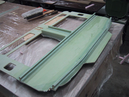
We had a huge roll of shrink wrap film, so two passes down the
table cover the whole thing. At the end of a session the whole
mess gets bundled up in a ball. Voila!... a clean table, OK
this is Randi's doing; she's the Queen of Neatness, I'm the Dark
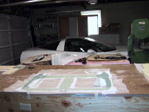
Mistress of Mess. She'll go as far as to put a wastebasket right
next to me (underfoot) but of course I'll fling that trimmed
ooey-gooey piece of cloth across the room (please note that I
fling NOTHING in the direction of Randi's corvette, see picture
above).
Because of the chemicals involved and the heat from exotherms we always put our days waste in a pile on the concrete floor till the next day rather than throw it in the trash dumpster.
We buy large rolls of wide plastic coated butcher paper in the super market. We always use this as our work surface. This stuff peels off after the parts set up and does not leave a wax residue like waxed paper would.
We peel ply everything in sight whether you see it or not. You never know when, where or what you may want to bond to a part in the future. It comes out better and smoother. Short of fine sand blasting there is no way to abrade 100% of a non peel plied surface without cutting through fibers.
We do all tapes and reinforcements on HD aluminum foil. Tape down a piece of foil (get the really HD stuff in wide rolls) dull side up on top of your bench, Do a marker layout on the foil, in the case of complex reinforcements like the hell hole and stuff around the main LG bulkheads it really helps to make a paper pattern, check the origami then transfer this to the foil, mark the, cut lines, bend lines etc. Lay up as many as 4 layers on the foil, cut, slit and fold till it looks like a wallet if needed, put into position and then carefully unfold each panel, smoothing out and pushing out air as you go. There is no need to remove the foil till the lay-up is completely burnished and squeegeed down. The foil prevents the plies from moving around. Peel off the foil and do a final check for bubbles and squeegee some more, peelply. Doing corner tapes this way is quick and easy, especially when you can lay out several on one width of foil, cut with your scissors, pre-fold and place.
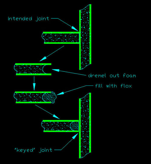
When
bonding two parts at 90 degrees, we use a Dremel with a ball-end
cutter to remove about 1/4" of the foam on the edge of the
bulkhead or part to be attached, fill this with flox to have it
"key" in to the intersecting bulkhead. This increases
the surface area of the bond.
***We
have not data to support our techniques, do at your own risk.
Trimming:
I can't say we ever really got proficient at nailing down the
"chewing gum" stage of resin cure and trimming the parts then. This
may in part be due to working on a lay-up till late, cleaning up
and going to bed.
Our original trim technique was one of scissor cutting as near as
possible without disturbing the lay-up and dealing with the
trimming when it setup.
But wait, there's great news! Much
later we discovered the wonderful Dritz Electric Scissors and
found 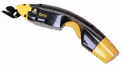 they
were perfect for trimming wet cloth. If you go around the part
counterclockwise it is possible to trim right to the very edge
of the foam; no post cure trimming required.
they
were perfect for trimming wet cloth. If you go around the part
counterclockwise it is possible to trim right to the very edge
of the foam; no post cure trimming required.
If I had a fine blade in the band saw it worked for trimming
some parts, watch that the lower side of the lamination is not
being pulled away from the foam. I found a table mounted router
with a ball bearing carbide laminate trimmer bit in it was
helpful for a lot of the flat parts.
My ever-present Dremel tool with a sanding drum is always handy
but the tool we wish we had acquired as early in the project as
possible would be the Fein
tool. There
is no way to prepare you for the joy this tool will bring you.
Notes
About The Parts:
Seat Back-
Other than the rectangular holes you make for the electrical
conduits, don't bother to cut the ovals for the control tubes.
Where the aileron torque tube holes are specified on the plans is not remotely close. We
are glad we heeded other peoples comments on this and only
marked where they are supposed to go and did not cut them out.
When I got to the point of needing the holes I came up with a
nifty method for getting them in right.
Instrument
Panel-
Everyone complains it comes out about .100"-.125"
short on the bottom edge; check the archives and adjust, easier
to trim off than to add.
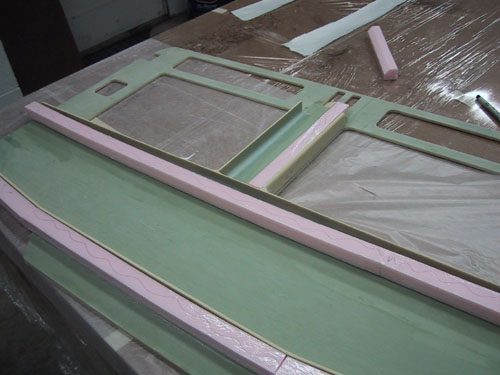
For the ribs on backside of the instrument panel; bond them in
place with flox first and do the upper BID tape between the rib
and the panel. Let cure then make some Styrofoam blocks to
support the lip. Cover foam with cello tape or duct tape. We
held these in place with double sided carpet tape.
When
we started this project we knew nothing about nifty products
like the Blue Mountain EFIS/One much less anything about what we
would eventually populate our panel with. We could never have
known I would eventually end up working for Blue Mountain
Avionics and redesigning the hardware. OK, I'll shamelessly
admit that I designed the displays to fit and look cool in
our plane... to what extent that was possible to get away with.
Only thing is, I did not design the plane to fit the system I
came up with. More on that later.
The instrument panel as built per plans is purely for
conventional instrumentation. There is a high probability we
will cut out the panel from the lower rib up leaving a one inch
tab on the fuselage sides to attach the new panel
to.
The instrument panel is an important structural member. When
removing material for instruments or modifying the panel this
should be kept in mind.
Firewall-
Check the archives and see there is a lot of angst and anger
resulting in following the plans method of anchoring these
screws... a couple of flats and some flox does not a secure
screw make. So we had to go improving the hell out of it. Given
this is an aircraft after all, "belt & suspenders"
security seems appropriate for any task, but we sort of took it
to 'belt & suspenders & rivets and glue...with flox".
I think our way was gross overkill and in the end may have its
own issues, time will tell.
So this is how we "improved" ours:
How
not
to embed the screws in the firewall...
-use Dremel tool to cut large slot in screw heads.
-cut oversized countersink in Firewall for screws.
-Dremel interconnecting channels in firewall to accommodate
pieces of wire.
-weld pieces of wire into slots of screws.
-bury whole mess in flox, put BID over it.
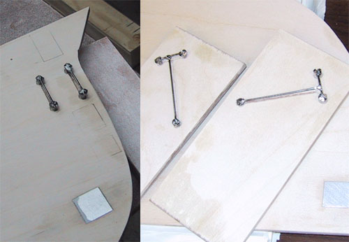
How
to bury screws in anything...
-drill appropriate size hole for screw.
-insert Click-Bond
screw.
-trace around large screw head.
-use Dremel router attachment to route a small recess.
-drill pattern of 6 holes in head of Click-Bond.
-clean head of Click-Bond with acetone and flox in position.
-apply 2 play BID patch approximately 2"x2" over
screws.
-for higher torque applications, insert rivet into one of the
holes previously drilled in the screw head.